Guide to PWM and PPM |
PWM and PPM are two common words used in the R/C industry. PWM stands for Pulse Width Modulation and PPM stands for Pulse Position Modulation. Some devices that use PWM for control are ESC's (electronic speed controls) and servos. PWM is a technique used to relay data in the form of a varying pulse width.
You may be already familiar with binary, 1's and 0's; where a 1 is represented as 'on' and a 0 as 'off'. An example of this would be a light switch. Turning the switch on would indicate a 1, off a 0. In the case of a PWM/PPM signal, a voltage applied indicates a 1 and vice versa. However, in the case of R/C electronics this 'on/off' data is not enough, this is where the pulse width comes in.
The way we relay data to a servo for instance is the time the pulse is on. In the case of R/C electronics this time is usually around 1-2 milliseconds. A servo or ESC will monitor this pulse and begin counting when the pulse is detected and stop counting when the pulse stops. The time the pulse is on will determine the servo position. For example, sending a servo a 1ms pulse will make the servo swing completely left while a 2ms pulse will swing the arm completely right.
Generally in R/C equipment an entire PWM pulse will last a total of 20ms. The entire pulse is called a frame. A complete frame will include both the time the pulse is high (1-2ms) and the time the pulse is low. The image below represents a typical PWM frame.
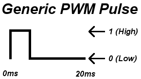
Although the frame lasts 20ms the important part of the pulse is the time the pulse is on; 1-2ms. Although the time between pulses is not as important it does play an important role. Usually keeping the time between pulses around 20ms is best. If the delay is longer, a servo for example will lose holding power. A pulse can be generated much faster but 20ms is best for most situations.
So what is the point in waiting up to 20ms? This is an R/C specific and will help understand PPM. Again, PPM stands for Pulse Position Modulation. PPM basically is several PWM signals lined up back to back. A PPM frame looks like this:
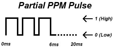
Aside from the gaining servo holding power, the reason for the 20ms frame is just having the ability to line up several PWM signals in the same frame. Like I said before, the time the pulse is on is what is important because we are able to strip out this relevant data from a PPM frame to re-generate a PWM frame. For example, if a radio only sent 1 PWM signal at a time, it would take 20ms per channel. If you have an 8 channel radio each update would take 160ms. The same data can be packed into a PPM frame and only take 20ms per update. Transmitters and receivers are the two most common R/C devices that use PPM.
The following are lists of common devices that use PPM and PWM.
R/C Devices that use PWM Pulses:
- Servos
- Electronic Speed Controllers
- R/C switches
- R/C lights
- R/C receivers
- Data loggers
- Failsafe's
- Autopilot/Stabilization systems
- Servo Controller
R/C Devices that use PPM Pulses:
- R/C transmitters
- R/C receivers
- Autopilot/Stabilization systems
- PCTx