
|
|
|
Adapters & Plugs
Analog Reader Audio Breakout Boards's Switches & Pots Cameras Development Failsafe's LCD's Motors Motor Control Pan & Tilts PCTx Power R/C Lights R/C Switches RoboRealm Sensors ServoCommander Servos Servo Accessories Servo Controllers Simulator Cables Software Trainer Cables Voltage Regulators
|
Using the WiFi Servo Controller to remotely water a garden
Project Requirements Only a few off the shelf components and basic plumbing knowledge are required to complete this project and it can be assembled and configured in less than a day. The items used in this sample are listed below. • WiFi Servo Controller and wired or wireless link to network
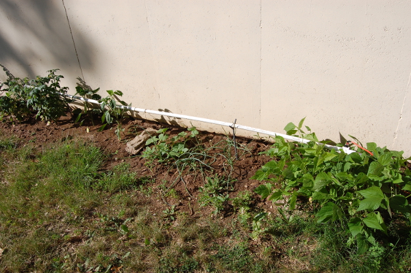
Setup Like previously mentioned, only off the shelf components are required for this project. No custom programming or hardware was necessary however there are a few areas where improvements can be made. In this example only the simple remote watering mechanisms were setup. One exception to this was the PVC piping system. Keep in mind that this setup was not necessary and standard sprinkler or trickle watering systems can be used. The first step was to mount the watering system. A section of ¾ PCV pipe was used to provide a watering system. Holes were drilled in the pipe very few inches and then capped off at the end. Water will enter through the valve and then drain out of the pipe. The pipe was mounted about 12 above the ground with steel steaks and wired in place. A standard garden hose was used to connect from the housing water supply to the valve. An adapter was necessary to convert the garden hose threads to the valve. All connections were sealed with PVC glue and Teflon tape to minimize leaks. See Figure 1. 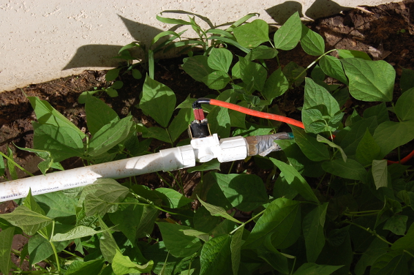 Figure 1. Solenoid valve and wiring in place
Once the hose and piping was constructed wiring was run to the valve solenoid and into the house. Since this would only be a temporary watering solution the wire was run into the house via an existing hole. The WiFi Servo Controller, BattleSwitch, and necessary power adapters were not left outside to prevent damage from the elements however if a waterproof enclosure was added it would be possible to leave everything outside and avoid running a wire through the house. Once the wiring was in place the WiFi Servo Controller and BattleSwitch were connected. Keep note of what channel you connect the BattleSwitch to. This is the channel that will need to be changed to activate the switch. Activating the flow of water through the valve is as simple as applying 12V to the valve. When power is not applied water will not flow. To accomplish this, the BattleSwitch needs to be able to control the flow of power through the 12V AC adapter. Placing the switch in between the ground or +12V line will accomplish this. See Figure 2 for a diagram of the electronics system.
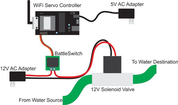 Figure 1. Solenoid valve and wiring in place
Configuring the network and WiFi Servo Controller for remote access over the internet will not be discussed in this article. A separate guide describing this setup can be found here: http://www.endurance-rc.com/wifi_net_config.php Once the wiring is connected power can then applied to the controller and the valve to complete the system. The system can be tested and run with the built in test page on the WiFi Servo Controller.
Usage Once the system is configured activating the water is as simple as calling up the test page and moving the appropriate slider to the max setting. The BattleSwitch can then be deactivated by moving the slider to the minimum setting and closing the test page.
Upgrades One of the main drawbacks of the current system is the lack of feedback. Once the slider is moved and the valve is activated you can only assume that the water is running. In order to fix this one good upgrade would be the addition of a camera or water flow sensor to verify the flow of water. A serial camera could easily be added to the system to monitor water flow. One other area that was overlooked was the rigidity of the hose. In order to control the flow of water the valve controlling the flow of water to the hose must be always open. This allows the electronic valve to control the water flow however it puts a lot of pressure on to the hose. In the case of the demo the hose had a pinhole leak causing a constant yet small leak. A better solution would be to use stiff PVC piping throughout the entire system. This however raises the cost but will minimize leaking.
Conclusion In the end it might be easier to get a neighbor to water your plants but it was a fun project. The project though was a success and as of the wriring of this article the plants have doubled in size so it does work! -Phil |